توپولوژی های تبدیل کننده ضریب توان یک مرحله ای تک فاز


27,600 تومانشناسه فایل: 7562
- حجم فایل ورد: 493.6KB حجم پیدیاف: 198KB
- فرمت: فایل Word قابل ویرایش و پرینت (DOCx)
- تعداد صفحات فارسی: 31 انگلیسی: 13
- دانشگاه:
- Department of Electrical and Computer Engineering, University of Western Ontario, London, ON N6G 1H1, Canada
- Department of Electrical and Computer Engineering, Queen's University, Kingston, ON K7L 3N9, Canada
- ژورنال: IEEE Transactions on Industrial Electronics (1)
چکیده
در مقاله حاضر، توپولوژی های مبدل اصلاح ضریب توان تک مرحله ای تک فاز شرح داده می شود. توپولوژی های بحث شده در این مقاله مرتبط با مبدل های AC-DC و AC-AC می باشند که مبتنی بر فرکانس خروجی منبع AC، حضور خازن لینک DC و نوع کنترل استفاده شده (رزونانسی یا مدولاسیون پهنای پالس) دسته بندی می شوند. اصول عملکرد کلی و نقاط قوت و ضعف کانورترها که نویسندگان در دهه گذشته بررسی کرده اند، به تفصیل بحث می شود و مناسب بودن آن ها در کاربردهای عملی بیان می شود. با توجه به محدودیتهای طراحی عملی، ممکن است بطور مؤثری تعداد زیادی از توپولوژیهای مبدل تک مرحله در رنج وسیعی از کاربردها بکارگیری شوند.
مقدمه مقاله
بطور کلی وظیفه ادوات الکترونیک قدرت، تبدیل توان الکتریکی قابل دسترس از منبع تغذیه به بهترین شکل مناسب برای بارهای مصرف کنندگان می باشد. نوعی از مبدل توان به عنوان رابط بین منبع تغذیه و بار برای رسیدن به این هدف نیاز می باشد. منبع تغذیه ورودی برای تجهیزات کمتر از 3KW، معمولاً منبع جریان متناوب (AC) تک فاز می باشد. مبدلها (کانورترها) ممکن است مبدل AC-DC یا AC-AC بستگی به نیاز بار با یا بدون ترانس ایزوله باشند.
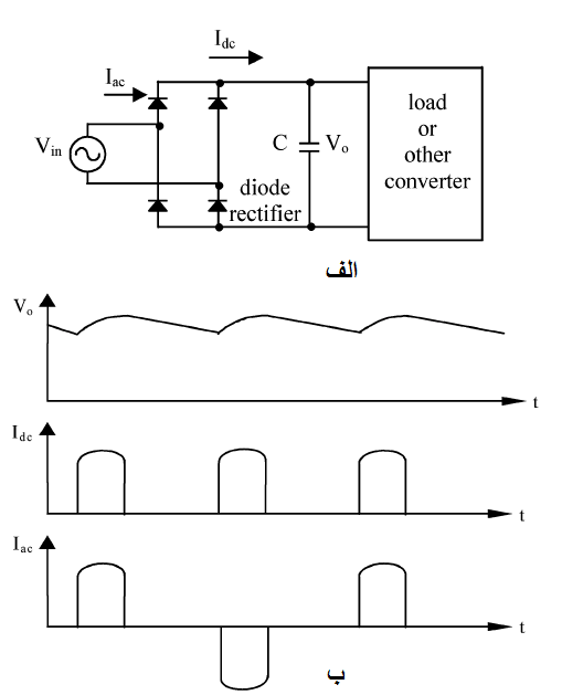
در گذشته استفاده از یکسو کننده پل دیودی تک فاز ساده با فیلتر خروجی خازنی همچنانکه در شکل (1) نشان داده شده است، به عنوان اولین سری مبدلها خیلی رایج بود.

پل دیودی، ولتاژ ورودی AC را یکسو می کند و خازن، ولتاژ خروجی را برای ایجاد یک موج DC خالص صاف می کند. با این وجود جریان کشیده شده از منبع کمکی AC غیر سینوسی است، زیرا دیودهای پل، جریان را فقط هنگامی هدایت می کنند که ولتاژ ورودی یکسو شده مساوی یا بزرگتر از ولتاژ خازن DC باشد.
پل دیودی نشان داده شده در شکل (1) به علت اینکه جریان غیر سینوسی از منبع می کشد ضریب توان ناچیزی دارد.
این جریان پیک خیلی بالایی دارد و شامل مولفه های هارمونیکی بزرگی است که به منبع تغذیه تزریق می شوند. اگر تعدادی زیادی از این مبدلها در صنایع استفاده شود هارمونیک های تزریق شده به منابع آنقدر زیاد است که نیاز است مقادیر ولتاژ و جریان نامی تجهیزات (مانند ترانسفورماتورها، خطوط انتقال و ژنراتورها) را افزایش داد و این هارمونیکها ولتاژ منبع را معوج می کنند. از آنجایی که یک منبع ولتاژ AC خیلی معوج شده می تواند به تجهیزات الکتریکی حساس (حساس به ولتاژ) آسیب وارد کند، سازمانهای نظارتی (آژانسهای نظارتی) در سراسر جهان استانداردهایی را برای محتوای هارمونیکی جریان تولید شده بوسیله تجهیزات برقرار کرده اند مانند EN61000-3-2 [1].
افزایش قابل توجه استفاده از تجهیزات الکتریکی در سالهای اخیر به علت افزایش تقاضای مصرف کنندگان، استفاده غیر مؤثر و ناکارآمدی از توان کمتر از حد قابل قبول نسبت به گذشته ایجاد کرده است.
استانداردهای سازمانهای نظارتی برای محتوای هارمونیکی، باعث معروف شدن یکسو کننده های پل دیودی ساده مانند کانورترهای جلو-انتهایی در عملکرد تجهیزات الکتریکی منابع AC شده است. علاوه بر این سازندگان تجهیزات الکتریکی مجبور به بهبود یا اصلاح ضریب توان ورودی تولیدات تغذیه شونده به وسیله منابع AC می باشند.
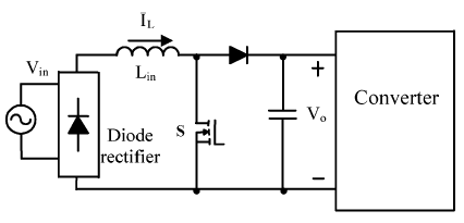
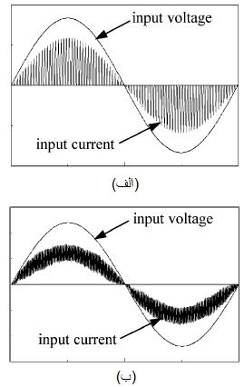
رایج ترین روش برای اصلاح ضریب توان (PFC) در کانورترهای AC-DC جلو-انتهایی، استفاده از کانورترهای بوست AC-DC با مدولاسیون پهنای پالس (PWM) می باشد که در شکل (2) نشان داده شده است و شکل موج های جریان ورودی نوعی آن در شکل (3) نشان داده شده است.


مبدل می تواند شکل موج های جریان ورودی که یا پیوسته و سینوسی همراه با مقداری رایپل می باشد و یا ناپیوسته و محدود به سینوسی با رایپل بیشتر تولید کند. جریان در هر دو مورد بطور مؤثری سینوسی است.
اگرچه ضریب توان ورودی عالی می تواند بوسیله استفاده از مبدل بوست PWM AC-DC همانند مبدل جلو-انتهایی در همه مبدل های AC-DC یا AC-AC دو مرحله ای بدست آید، ولی اگر از یکسوکننده پل دیودی بجای آن استفاده شود مبدل گرانتر و پیچیده تر می شود. این بدین دلیل است که دو مرحله مبدل سوئیچ زنی مجزا در نیاز به یک کنترلر مجزا وجود دارد.
محققان الکترونیک قدرت جهت کاهش هزینه و پیچیدگی مبدلهایی که با ضریب توان بهتری نسبت به مبدل های با یکسوساز پل دیودی AC-DC جلو- انتهایی کار می کنند، مبدلهایی را که ترکیبی از توابع تبدیل توان و اصلاح ضریب توان در یک مبدل تکی می باشند پیشنهاد کرده اند.
تبدیل توان یک مرحله ای یک موضوعی است که جلب توجه محققان الکترونیک قدرت در سالهای اخیر شده است و مبدلهای زیادی پیشنهاد شده اند. این مبدل ها بطور کلی بر طبق دیاگرام نشان داده شده در شکل (4) دسته بندی می شوند.

در این مقاله تعدادی از مبدلهای تک مرحله ای بر طبق این دسته بندی مرور می شوند.
مباحث مربوط به هر نوع مبدل بحث می شود و روشهای گوناگونی برای اصلاح ضریب توان (PFC) بررسی می شود. نقطه تمرکز مقاله بر روی مبدلهای تک مرحله ایی خواهد بود که نویسندگان در دهه گذشته بررسی کرده اند. نکات کلیدی در انتهای مقاله خلاصه شده است.
ABSTRACT Single-phase single-stage power-factor-corrected converter topologies
Single-phase single-stage power-factor-corrected converter topologies are reviewed in this paper. The topologies discussed in the paper are related to ac-dc and ac-ac converters that are classified on the basis of the frequency of the input ac source, the presence of a dc-link capacitor, and the type of control used (resonant or pulsewidth modulation). The general operating principles and strengths and weaknesses of the converters, which the authors have investigated over the last decade, are discussed in detail, and their suitability in practical applications is stated. Considering practical design constraints, it is possible to effectively employ many single-stage converter topologies in a wide range of applications.
Introduction
It is generally the task of power electronics to convert the electric power available from a power source into the form best suited for user loads. Some sort of power converter is required to serve as an interface between power source and load to achieve this objective. The input power source for equipment handling less than 3 kW of power is usually a single-phase ac source. The converter itself may be an ac–dc or an ac–ac converter, with or without transformer isolation, depending on the requirements of the load.
It was very common in the past to use a simple, single-phase diode bridge rectifier with a capacitive output filter as the first stage of the converter as is shown in Fig. 1. The diode bridge rectifies the ac input voltage and the capacitor smoothes out the resulting voltage to make it an almost pure dc waveform. The current drawn from the ac utility source, however, is very nonsinusoidal because the bridge diodes conduct current only when the rectified input voltage is equal to or greater than the dc capacitor voltage. It is only then that current flows to charge the capacitor.
For any electrical equipment drawing power from the utility, the input power factor is an indication how effectively this is accomplished. The diode bridge rectifier shown in Fig. 1 has a poor power factor because of the non sinusoidal current it draws from the utility. This current has a very high peak and contains large harmonic components that are injected into the utility supply. If vast numbers of such converters were to be used in industry, the harmonics that would be injected in the utility would be so large that they would create a need for increased volt-ampere ratings of utility equipment (i.e., transformers, transmission lines, and generators) and distort the utility voltage. Since a severely distorted ac utility voltage can damage sensitive electrical equipment, regulatory agencies around the world have established standards on the current harmonic content produced by electrical equipment, such as EN61000-3-2 [1]. The significant rise in the use of electrical equipment in recent years due to increased consumer demand has made the inefficient use of power less tolerable than in the past.
Stricter regulatory agency standards on harmonic content have led to the demise in popularity of the simple diode-bridge rectifier as the front-end converter in electrical equipment operating off of an ac supply. More and more, electrical equipment manufacturers are being forced to improve or “correct” the input power factor of products supplied by an ac utility source.
The most common approach to power factor correction (PFC) in a front-end ac–dc converter is to use an active, pulsewidth-modulated (PWM) ac–dc boost converter, which is shown in Fig. 2 along with some typical input current waveforms in Fig. 3. The converter can produce input current waveforms that are either continuous and sinusoidal with some ripple, or discontinuous and bounded by a sinusoidal envelope with substantially more ripple. The current in both cases is effectively sinusoidal.
Although an excellent input power factor can be achieved by using an ac–dc PWM boost converter as the front-end converter in an overall two-stage ac–dc or ac–ac converter, the overall converter becomes more expensive and complicated than it would be if a diode-bride rectifier were used instead. This is because there are two separate switching converter stages present, each requiring a separate controller. In order to reduce the cost and complexity of the overall converter, yet operate with a power factor better than that produced by a converter with a front-end ac–dc diode-bridge rectifier, power electronics researchers have proposed converters that combine the PFC and power conversion functions in a single converter.
Single-stage power conversion is a topic that has been of substantial interest to power electronics researchers in recent years, and numerous converters have been proposed. These converters can generally be classified according to the diagram shown in Fig. 4. In this paper, a number of single-stage converters will be reviewed according to this classification. The issues associated for each converter type will be discussed and various approaches for PFC will be examined. The focus of the paper will be placed on single-stage converters that the authors have investigated over the past decade. The key points of the paper will be summarized at the end.


![مبدل فوروارد AC-DC تک سوئیچه تک مرحله ای با سیم پیچ ترانسفورماتور پیشنهاد شده در مرجع ]8[ (سیم پیچ مغناطیس زدا نشان داده نشده است)](https://maghalejoo.com/wp-content/uploads/2019/03/13/img-11.png)


- مقاله درمورد توپولوژی های تبدیل کننده ضریب توان یک مرحله ای تک فاز
- توپولوژی های کانورترهای ضریب توان یک مرحله ای تک فاز
- پروژه دانشجویی توپولوژی های تبدیل کننده ضریب توان یک مرحله ای تک فاز
- مکان شناسی تبدیل کننده ضریب قدرت تک مرحله ای تک فاز
- پایان نامه در مورد توپولوژی های تبدیل کننده ضریب توان یک مرحله ای تک فاز
- تحقیق درباره توپولوژی های تبدیل کننده ضریب توان یک مرحله ای تک فاز
- مقاله دانشجویی توپولوژی های تبدیل کننده ضریب توان یک مرحله ای تک فاز
- توپولوژی های تبدیل کننده ضریب توان یک مرحله ای تک فاز در قالب پاياننامه
- پروپوزال در مورد توپولوژی های تبدیل کننده ضریب توان یک مرحله ای تک فاز
- گزارش سمینار در مورد توپولوژی های تبدیل کننده ضریب توان یک مرحله ای تک فاز
- گزارش کارورزی درباره توپولوژی های تبدیل کننده ضریب توان یک مرحله ای تک فاز
